Central Nexus First Electronic Seismograph Details
The Introduction
This page describes how I made my first electronic seismograph with an ADXL 345 acceleromter. The video shows a good overview of how it works.
This was the first video I made of the seismomometer. I used a breadboard to prototype the layout.
The Setup
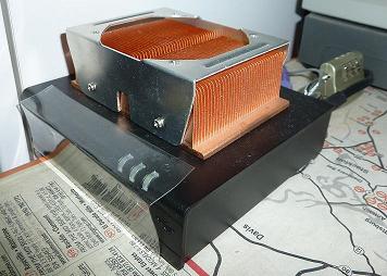
The setup uses a low power CompuLab fit-PC2. I added a 40GB SSD drive and installed Ubuntu Server Linux to it. It normally consumes less than 10 watts, but the heat sink is a good idea since it's running in my garage, which can go well beyond the normal working temperatures of a computer. I connect the Arduino microcontroller to this computer via a USB cable. The Arduino is connected to the ADXL 345 accelerometer. My next revision has improved sensitivity by using a different accelerometer, but the general configuration is mostly the same.
A picture of the computer recording the data. It's really small.
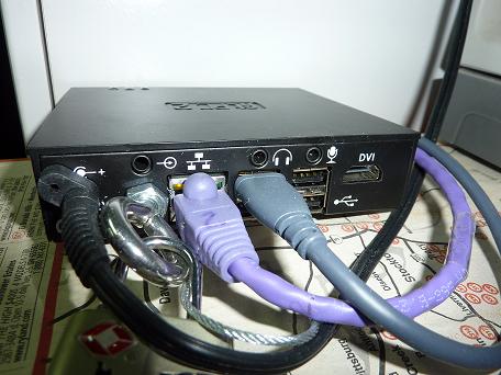
The back of the computer. I replaced the wifi antenna with a bolt to prevent people from stealing it.
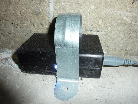
The sensor in a sleek black box with an LED showing through. The light is blue. So it's sensing gravity in the Z axis.
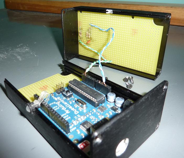
The sensor is enclosed in a project box and hooked up to the Arduino Duemilanove microcontroller. I got the aluminum project box and PC board from Fry's. The box has slots on the inside that make it easy to slide in the PC board that I cut to size.
The inside of the sensor.
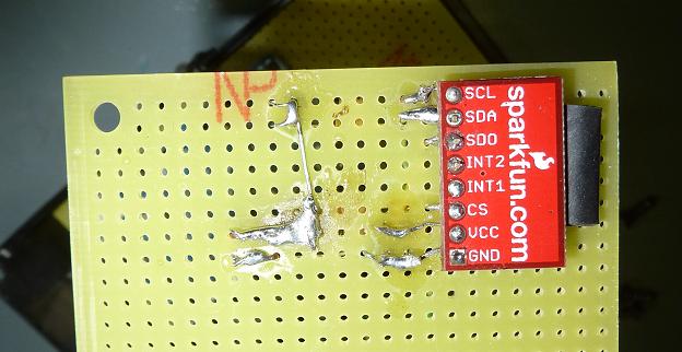
Top view of the ADXL345 accelerometer. Please excuse my soldering technique.
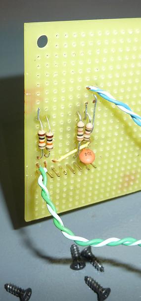
Bottom view of the ADXL345 accelerometer.
The Source Code
Below is the code I wrote for the Arduino microcontroller. The original code also controls a tricolor LED, but I stripped that out to make the code a little cleaner for others to view. The LED was helpful for ensuring that the output on the screen is what was the sensor was really reading. I'm using the I²C protocol to communicate with the ADXL345 sensor. This code requires the 2Wire library from the Arduino development environment.
 /*
 Copyright (c) 2010 George Rhoten

 Permission is hereby granted, free of charge, to any person obtaining a copy
 of this software and associated documentation files (the "Software"), to deal
 in the Software without restriction, including without limitation the rights
 to use, copy, modify, merge, publish, distribute, sublicense, and/or sell
 copies of the Software, and to permit persons to whom the Software is
 furnished to do so, subject to the following conditions:

 The above copyright notice and this permission notice shall be included in
 all copies or substantial portions of the Software.

 THE SOFTWARE IS PROVIDED "AS IS", WITHOUT WARRANTY OF ANY KIND, EXPRESS OR
 IMPLIED, INCLUDING BUT NOT LIMITED TO THE WARRANTIES OF MERCHANTABILITY,
 FITNESS FOR A PARTICULAR PURPOSE AND NONINFRINGEMENT. IN NO EVENT SHALL THE
 AUTHORS OR COPYRIGHT HOLDERS BE LIABLE FOR ANY CLAIM, DAMAGES OR OTHER
 LIABILITY, WHETHER IN AN ACTION OF CONTRACT, TORT OR OTHERWISE, ARISING FROM,
 OUT OF OR IN CONNECTION WITH THE SOFTWARE OR THE USE OR OTHER DEALINGS IN
 THE SOFTWARE.
 */
#include <Wire.h>

// ADXL345
#define DEVICE ((byte)0x53)    //ADXL345 device address

#define BW_RATE  	0x2C	//Data rate and power mode control.
#define POWER_CTL	0x2D	//Power Control Register
#define DATA_FORMAT	0x31	//Data format control
#define DATAX0		0x32	//X-Axis Data 0
#define DATAX1		0x33	//X-Axis Data 1
#define DATAY0		0x34	//Y-Axis Data 0
#define DATAY1		0x35	//Y-Axis Data 1
#define DATAZ0		0x36	//Z-Axis Data 0
#define DATAZ1		0x37	//Z-Axis Data 1

//Writes val to address register on device
static void writeTo(byte address, byte val) {
   Wire.beginTransmission(DEVICE); //start transmission to device
   Wire.send(address);        // send register address
   Wire.send(val);            // send value to write
   Wire.endTransmission();    //end transmission
}

// Throw away everything in the queue
// Call this if we've lost track of where we are in the data stream.
static void flushBus() {
  while(Wire.available()) {
    Wire.receive();
  }
}

//reads num bytes starting from address register on device in to buff array
static void readFrom(byte address, byte num, byte *buff) {
  Wire.beginTransmission(DEVICE); //start transmission to device
  Wire.send(address);        //sends address to read from
  Wire.endTransmission();    //end transmission

  Wire.requestFrom(DEVICE, num);  // request num bytes from device
  byte availSize = Wire.available();
  if (availSize != num) {    //device may send less than requested (abnormal)
    delay(1);
    flushBus();
    return -1; // return error
  }
  while(availSize-- > 0) {
    *(buff++) = Wire.receive(); // receive a byte
  }
  return num;
}

void setup()
{
  Wire.begin();          // join i2c bus (address optional for master)
  Serial.begin(115200);  // start serial for output
  Serial.flush();

  writeTo(BW_RATE, 0xB); // Ensure refresh rate
  writeTo(POWER_CTL, 8); // Turn on the ADXL345 measuring mode

  // Wait for readings to settle down.
  delay(10);
}

void loop()
{
  // 2 byte endian marker
  // 6 byte buffer for saving data read from the device
  // 2 byte checksum in case there is a reset in the middle of a packet.
  int axis[5] = {0x8081, 0, 0, 0, 0};

  //Read the acceleration data
  //Each axis reading comes in 10 bit resolution (2 bytes little endian).
  while (readFrom(DATAX0, BYTES_PER_SAMPLE, (byte*)(axis+1)) != BYTES_PER_SAMPLE) {
    // We reread if we don't get the amount we wanted.
  }

  // Calculate checksum.
  axis[4] = axis[1] + axis[2] + axis[3];
  // Write whole packet.
  Serial.write((byte *)axis, sizeof(axis));
/*  Serial.print(axis[1], DEC);
  Serial.print('\t');
  Serial.print(axis[2], DEC);
  Serial.print('\t');
  Serial.println(axis[3], DEC);*/

  // Wait a little bit.
  delayMicroseconds(6250 - (int)(micros() % 6250));
}
The Code To Read The Sensor
Sorry, but the source code I wrote to display the graphs is not yet ready to be consumable for the public. You can use the compiled version in the mean time. It includes the required RXTX libraries that are required to interface with the Arduino microcontroller. The program requires Java, and it's been tested to work on Windows, Linux and Mac OS X. When reading from the sensor, the data is written to files in the ${user.home}/RhoSeis/ directory.
If you need more information on interfacing with the Arduino microcontroller by using Java, you may find the Arduino Java tutorial helpful when reading this sensor.