|
|
Central Nexus Seismograph Project Details
The Setup
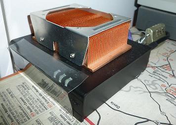
The setup uses a low power CompuLab fit-PC2. I added a 40GB SSD drive and installed Ubuntu Server Linux to it. It normally consumes less than 10 watts, but the heat sink is a good idea since it's running in my garage, which can go well beyond the normal working temperatures of a computer. I connect the Arduino microcontroller to this computer via a USB cable. The entire configuration is attached to my UPS to ensure that it continues recording during a power outage, which is possible after strong earthquakes.
A picture of the computer recording the data. It's really small.
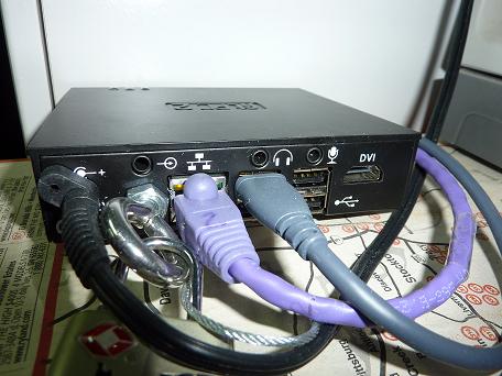
The back of the computer. I replaced the wifi antenna with a bolt to prevent people from stealing it.
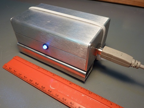
The sensor in an aluminum box with an LED showing through on top of a small leveling table. The light is blue. So it's sensing gravity in the Z axis.
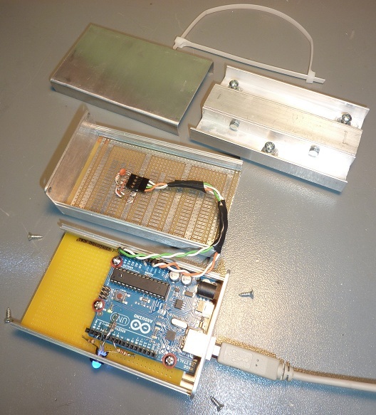
The inside of the seismometer sensor.
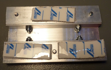
The bottom of the hand crafted leveling table with velcrow. I bolted together 3 u-shaped pieces of aluminum. The three bolts on the bottom are used to adjust the height to provide a level surface for the seismometer.
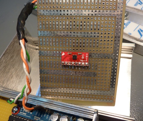
The BMA180 accelerometer.
The Shopping List
The following is a list of items that I used in case you want to assemble something similar. Think of it as a recipe for making your own sensor.
| Part | Needed? | Comment |
| CompuLab fit-PC2 |
Required |
Almost any fanless computer will do. |
| 40 GB SSD hard drive |
Required |
Has no moving parts. Larger capacity is better. |
| UPS |
Optional |
Good for power outages. |
| USB cable |
Required |
Connects computer to Arduino. |
| Aluminum enclosure |
Required |
Protects all parts. Mine was bought at Fry's. The internal slots are used to hold the boards.
|
| Arduino Uno |
Required |
Some other variants are usable. |
| Wire |
Required |
Spare Ethernet cable wire was used. |
| Electrical tape |
Optional |
Helpful to prevent movement of wire. |
| Leveling table |
Optional |
Makes it easier to attach sensor to floor. |
| Aluminum trim channel |
Required |
Cut into 3 pieces that are as long as the enclosure. Trim for ¾" plywood was used.
|
| 7 bolts |
Required |
Pick something not too large nor too small. |
| 4 locking nuts |
Required |
Prevents table from falling appart. |
| Small aluminum sheet |
Required |
Cut and bend to cover top. |
| Superglue |
Required |
Attaches nuts for leveling bolts to table. |
| Velcrow |
Required |
Attaches bottom of table to floor. Can be substituted for a bolt attached to floor. |
| 2 zip ties |
Required |
Attaches sensor to table. |
| 1 tricolor LED |
Optional |
Provides visual feedback on health. |
| 3x100Ω resistors |
Required |
Reduces flicker of LED. |
| LED grommet |
Optional |
Attaches the LED to enclosure. |
| Breadboard (plugboard) |
Optional |
Helpful for testing setup before final assembly. |
| Prototype board with plated holes |
Required |
Mount the accelerometer to this board. |
| Prototype board without plated holes |
Optional |
Mount the Arduino to this board. |
| 4 small bolts |
Required |
Attaches Arduino to prototype board. |
| Male breakaway header |
Optional |
Helpful for testing and mounting accelerometer. You can use just wire instead. |
| 4 pin connector |
Optional |
Connect to breakaway header and wire. |
| Bosch Sensortec BMA180 accelerometer |
Required |
Get the one with the breakout board from sparkfun.com. |
| 10 nF capacitor |
Optional |
Reduces signal noise by a small amount. Connect to VDD and ground closest to chip. |
| 1000 µH RF choke |
Optional |
Reduces signal noise by a small amount. Connect inline to only VDD. |
The following are some tools used to assemble the parts.
| Tools | Comment |
| Soldering iron & solder |
Required for breakout board. |
| Drill & drill bits |
Makes holes in enclosure and table. |
| Metal file |
Smooths rough edges. |
| Hack saw |
Needed for cutting aluminum trim channel. |
| Metal sheers |
Needed for cutting prototype board. |
| Screwdriver |
Needed for assembly. |
| Pliers |
Needed for tightening nuts. |
| Needlenose pliers |
Needed for handling wire and pins. |
Assembly Suggestions
The BMA180 accelerometer sensor is enclosed in a project box and hooked up to the Arduino Uno microcontroller. I got the aluminum project box and PC board from Fry's. The box has slots on the inside that make it easy to slide in the PC board that I cut to size. The Arduino already has the required pull up resistors for the analog pins 4 and 5. The optional tricolor LED needs a 100 Ohm resistor for each color. The LED provides some visual queues to show what the accelerometer is sensing while not displaying output to a graphing program. The varying colors of the light also look cool when you move it around!
Soldering the components together is not easy. If you have not soldered before, I recommend looking at some Youtube videos and practicing your technique. The accelerometer was soldered last to minimize any damaging heat exposure or in case a mistake is made during the wiring process. Double check your wiring before finishing the soldering with the accelerometer to ensure there are no shorts. Shorts are easier to fix without the accelerometer in the way.
To save on costs, you could use a single prototype board to assemble everything together, but using separate prototype boards makes it easier to upgrade and replace any parts. All parts, like these prototype boards, should be fitted snuggly to ensure nothing rattles during any shaking and add noise to any shaking readings.
Installation
The velcrow under the leveling table is used to attach to a sturdy surface like a cement floor. To really make sure that the motion is transferred to the sensor, the velcrow can be substituted with a single bolt attached to a cement floor, but that would require making a hole in the cement to attach the bolt. Wood flooring dampens some of the motion. When attaching the sticky side of the velcrow, the floor surface should be cleaned to ensure a solid attachement.
Normally, one of the axes is aligned to North. Orienting the sensor will make it easier to correlate the motion to a map.
The bolts in the leveling table are used like a tripod to level the surface for the sensor. The metal plate for the top of the table can be remove to adjust these bolts. It's a good idea to level the top with a level. Since the accelerometer may need some calibration, it's a better idea to use a level than the accelerometer. The accelerometer may need some calibration to ensure the data is accurately recorded.
The computer recording the data is synchronized to an NTP server on the Internet. This will ensure that the time of any shaking is accurately recorded. Some of the smaller earthquakes may barely register above the noise floor of the accelerometer. Accurate timing will make it easier to narrow down your search in the data by correlating the time with the recorded earthquake events from the USGS web site.
The BMA180 Accelerometer
The BMA180 accelerometer in this seismometer is fairly sensitive, but it's not as sensitive as professional seismographs used by the USGS. It's still an order of magnitude better than my previous seismometer that used the ADXL345 accelerometer. Considering that the cheapest seismometers can cost several thousand dollars, and I want to measure earthquakes that can actually be felt, I'm okay to spend just a few hundred dollars for the entire configuration. Most of my cost was for the low power computer to log and analyze the data. This set up is 1-2 orders of magnitude cheaper than the professional ones, and at least 2 orders of magnitude more expensive than my first seismograph.
When leveled correctly, and mounted sturdily, the noise can spike to about 0.5% gravity. 90% of that noise is in a band of about 0.3% of gravity. When it's not leveled, the readings have a tendency to have unidirectional spikes to > 1.5% of gravity. These unidirectional spikes are unnatural movement when compared to natural shaking movement. Natural shaking tends to affect all axes and tends to vibrate like a pendulum, which is a back and forth motion. These numbers do depend on the settings you have configured for your chip. The mode_config and bandwidth settings primarily change the amount of noise in the readings, but the offset settings also seem to affect the amount of unidirectional spikiness. So some experimentation with the settings is needed to reduce the amount of noise.

The initial sensor with unidirectional spikes every few seconds.

Calibrated sensor with a more constant level of noise.
When calibrating or verifying the offset, it's a good idea to calibrate on a level surface. The sensor can be placed on the level surface. The axis value can be read for gravity in one direction, then you can flip it 180° and read the gravity value in the opposite direction. When the offset is correct, the absolute value of the positive and negative values should be the same.
You can optionally add a small capacitor between the ground and the voltage supply. This can reduce the noise in the readings by a small amount. The BMA180 documentation recommends decoupling the VDD and VIO voltage, but I'm unaware of a way to do that. A small inline inducer with a small capacitor connected to ground may help to decouple the voltage between the VDD and VIO lines. The wiring diagram below is the minimum that is required to read the accelerometer.
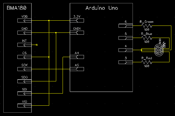
The wiring diagram to hook up the BMA180. I did not attach the interrupt pin.
The Source Code
Below is the source code I wrote for the Arduino microcontroller. It requires the Arduino development environment to work. The code normally reads the accelerometer, writes it out to the USB connection, and adjust the LED levels to the current sensed acceleration. I'm using the I²C protocol to communicate with the BMA180 sensor. This code requires the 2Wire library from the Arduino development environment.
/*
Copyright (c) 2010-2011 George Rhoten

Permission is hereby granted, free of charge, to any person obtaining a copy
of this software and associated documentation files (the "Software"), to deal
in the Software without restriction, including without limitation the rights
to use, copy, modify, merge, publish, distribute, sublicense, and/or sell
copies of the Software, and to permit persons to whom the Software is
furnished to do so, subject to the following conditions:

The above copyright notice and this permission notice shall be included in
all copies or substantial portions of the Software.

THE SOFTWARE IS PROVIDED "AS IS", WITHOUT WARRANTY OF ANY KIND, EXPRESS OR
IMPLIED, INCLUDING BUT NOT LIMITED TO THE WARRANTIES OF MERCHANTABILITY,
FITNESS FOR A PARTICULAR PURPOSE AND NONINFRINGEMENT. IN NO EVENT SHALL THE
AUTHORS OR COPYRIGHT HOLDERS BE LIABLE FOR ANY CLAIM, DAMAGES OR OTHER
LIABILITY, WHETHER IN AN ACTION OF CONTRACT, TORT OR OTHERWISE, ARISING FROM,
OUT OF OR IN CONNECTION WITH THE SOFTWARE OR THE USE OR OTHER DEALINGS IN
THE SOFTWARE.
*/

/*
If you need some reference material take a look at the following:

Instrumentation in Earthquake Seismology (Modern Approaches in Geophysics)
  by Jens Havskov, Gerardo Alguacil

BMA180 digital, triaxial acceleration sensor data sheet
  by Bosch Sensortec

The original source code can be found at:
http://www.centralnexus.com/seismograph/details_bma180.html
*/
#include <Wire.h>

// ADXL345
#define DEVICE ((byte)0x40)    //BMA180 device address

#define DATA_X0		0x02	//X-Axis Data 0
#define DATA_X1		0x03	//X-Axis Data 1
#define DATA_Y0		0x04	//Y-Axis Data 0
#define DATA_Y1		0x05	//Y-Axis Data 1
#define DATA_Z0		0x06	//Z-Axis Data 0
#define DATA_Z1		0x07	//Z-Axis Data 1
#define DATA_TEMP	0x08	//Temperature
#define SOFT_RESET	0x10	//soft_reset
#define SOFT_RESET_VAL	0xB6	//soft_reset value to reset

#define AXIS_SHIFT	2	//Amount to right shift data. The first 2 bits are status bits.

// USGS suggests rates of 20, 40 or 200 samples per second for natural earthquakes.
//#define DELAY_RATE	9990	//~100Hz
//#define DELAY_RATE	6600	//~150Hz
#define DELAY_RATE	4993	//~200Hz

// LED
#define COMMON_ANODE 4
#define RED_PIN 3
#define BLUE_PIN 5
#define GREEN_PIN 6
#define LED_VALUE_SHIFT 4

#define GRAVITY 255
#define ANALOG_MAX 0xFF
#define USE_LED 1

/**
 * The value in relation to 0xFF within the range value.
 */
static byte pinMagnitudeRangeToTop(byte range, int value) {
  if (value < 0) {
    value = -value;
  }
  if (value > 255) {
    return (byte)ANALOG_MAX - range;
  }
  return (byte)ANALOG_MAX - (byte)(((float)value / (float)GRAVITY) * (float)range);
}

//Writes val to address register on device
static void writeTo(byte address, byte val) {
  Wire.beginTransmission(DEVICE); //start transmission to device
  Wire.send(address);        // send register address
  Wire.send(val);        // send value to write
  Wire.endTransmission(); //end transmission
}

//reads num bytes starting from address register on device in to buff array
static void readFrom(byte address, byte num, byte *buff) {
  Wire.beginTransmission(DEVICE); //start transmission to device
  Wire.send(address);        //sends address to read from
  Wire.endTransmission(); //end transmission

  Wire.requestFrom(DEVICE, num);    // request num bytes from device
  num = Wire.available(); //device may send less than requested (abnormal)
  while(num-- > 0) {
    *(buff++) = Wire.receive(); // receive a byte
  }
}

/**
 * Writes val to address register on device if it's different from
 * the current value. This decreases the wear and tear on the EEPROM.
 */
static void writeOptionallyTo(byte address, byte val, byte mask) {
  byte value = 0;
  readFrom(address, sizeof(value), &value);
  if ((value & mask) != (val & mask)) {
    // Keep the unmasked values, and changed the masked values.
    writeTo(address, (value & ~mask) | (val & mask));
  }
}


void setup()
{
  Wire.begin();          // join i2c bus (address optional for master)
  Serial.begin(115200);  // start serial for output
  Serial.flush();

  // Wait for readings to settle down.
  // 10ms Pause is required to write registers.
  delay(15);

  writeOptionallyTo(0x0D, 0x10, 0x10); // Enable register write

  // I can't figure out how to modify the EEPROM.
  // So we reset upon startup.

  // Change calibration values based on new mode.
  // Each chip will need their own calibration.
  // Note: some offset values affect the spikiness of the values. You should test your values.
  writeOptionallyTo(0x3A, 0x76, 0xFF); // original offset MSB z=0x78 when mode_config=0
  writeOptionallyTo(0x39, 0x5C, 0xFF); // original offset MSB y=0x60 when mode_config=0
  writeOptionallyTo(0x38, 0x6D, 0xFF); // original offset MSB x=0x70 when mode_config=0
  writeOptionallyTo(0x36, 0x7C, 0xFF); // original offset LSB z=0x4, y=0xC when mode_config=0
  // Need a range of existing gravity + 1 G movement to get up to a 9.0M earthquake.
  writeOptionallyTo(0x35, 0xC4, 0xFF); // original offset LSB x=0x1, range+12bit=0x4 when mode_config=0

  writeOptionallyTo(0x30, 0x01, 0x03); // Change mode_config to lower noise mode
  writeOptionallyTo(0x21, 0x00, 0x04); // Turn off adv_int

  /* Earthquakes have a nominal frequency range of 0.001–50 Hz. The P and S
   * waves of >2.0M earthquakes usually have a frequency of 0.1-10 Hz. The
   * higher frequencies are attenuated by the bedrock. So you need to be
   * close to the epicenter to measure the higher frequencies. In order to
   * accurately record the lower frequencies, the bandwidth measurement must
   * be lowered in the sensor. When equal to 0x8 or 0x9, the gravity will be
   * cancelled out.
   */
  writeOptionallyTo(0x20, 0x20, 0xF0); // Change bandwidth. 0x2=40Hz 0x3=75Hz Originally 0x4

  writeOptionallyTo(0x0D, 0x00, 0x10); // Disable register write for protection

#if USE_LED
  //3 color LED
  pinMode(COMMON_ANODE, OUTPUT);
  digitalWrite(COMMON_ANODE, HIGH);

  pinMode(RED_PIN, OUTPUT);
  digitalWrite(RED_PIN, HIGH);

  pinMode(GREEN_PIN, OUTPUT);
  digitalWrite(GREEN_PIN, HIGH);

  pinMode(BLUE_PIN, OUTPUT);
  digitalWrite(BLUE_PIN, HIGH);
#endif
}

void loop()
{
  // 2 byte endian marker
  // 6 byte buffer for saving data read from the device
  // 2 byte checksum in case there is a reset in the middle of a packet.
  int axis[5] = {0x8081, 0, 0, 0, 0};

  // There are 1,000,000 microseconds per second,
  // and we want to sample about 200 per second.
  // This gives us about the right rate with the rest of the overhead.
  delayMicroseconds(DELAY_RATE - (int)(micros() % DELAY_RATE));

  // Each axis reading comes in 14 bit resolution (2 bytes little endian).
  readFrom(DATA_X0, 6, (byte*)(axis+1)); //read the acceleration data

  // Remove status and 0 bits
  axis[1] = axis[1] >> AXIS_SHIFT;
  axis[2] = axis[2] >> AXIS_SHIFT;
  axis[3] = axis[3] >> AXIS_SHIFT;

  // Calculate checksum.
  axis[4] = axis[1] + axis[2] + axis[3];
  // Write whole packet.
  Serial.write((byte *)axis, sizeof(axis));

#if USE_LED
  analogWrite(RED_PIN, pinMagnitudeRangeToTop(0xFF, axis[1]>>LED_VALUE_SHIFT));
  analogWrite(GREEN_PIN, pinMagnitudeRangeToTop(0xFF, axis[2]>>LED_VALUE_SHIFT));
  analogWrite(BLUE_PIN, pinMagnitudeRangeToTop(0xFF, axis[3]>>LED_VALUE_SHIFT));
#endif
}
The Code To Read The Sensor
Sorry, but the source code I wrote to display the graphs and archive the data is not yet ready to be consumable for the public. You can use the compiled version in the mean time. It includes the required RXTX libraries that are required to interface with the Arduino microcontroller. The program requires Java, and it's been tested to work on Windows, Linux and Mac OS X. When reading from the sensor, the data is written to files in the ${user.home}/RhoSeis/ directory.
The program I wrote writes the data in its own format. It doesn't write it in more portable common formats like SAC, SEED or MSEED yet. While the program does write the data accurately, it does not provide accurate analysis for earthquake magnitudes. It's pretty much only good for storing and visualizing the data.
If you need more information on interfacing with the Arduino microcontroller by using Java, you may find the Arduino Java tutorial helpful when reading this sensor.
|
